Maxitronix-30in1-01
This is project #1 of the Maxitronix-30in1: Intro Project (with fix from Jason Jacques).
The KiCad project is here: Maxitronix-30in1-01-2.tgz.
See KiCad for some notes about my KiCad configuration.
While working on this project I asked a question over on the EEVblog Forum: How to model transformer in KiCad 9.0 for SPICE simulation.
Discussion
Feedback from Jason Jacques
Our mate Jason Jacques sent in a modification for our circuit: Science Fair 30 in One Electronic Projects Lab - Experiment Circuit 1 Fix (CircuitJS Simulation). The Science Fair 30 in One Electronic Projects Lab is basically the same as our Maxitronix-30in1, just branded differently. His notes follow.
The proposed modification is:

This video shows a CircuitJS simulation of a minor change to Project 1 from the Tandy Radio Shack Science Fair 30 in One Electronic Projects Lab (also sold as the Maxitronix 30 in 1), that allows the circuit to operate as advertised in the project description: allowing the tone to be adjusted by pressing and releasing the key.
- Project 1. Instructions (on Page 2): https://www.radioshackcatalogs.com/flipbook/m-science_fair_kits_30-in-1_electronic_projects_lab_28-161.html

- Project 1. Schematic (on Pages 64/65): https://www.radioshackcatalogs.com/flipbook/m-science_fair_kits_30-in-1_electronic_projects_lab_28-161.html

This ability to raise and lower the tone by completing and breaking the switch path is also described in this, essentially identical, circuit from the 60-in-1 kit (28-256) which uses a magnetic reed switch and magnet in place of the key.
- Project 28. Electronic Siren (on Page 33): https://www.radioshackcatalogs.com/flipbook/m-science_fair_kits_60-in-1_electronic_project_lab_28-256.html

Equally, while there are significant changes to the component values, due to the increased operating voltage, a similar circuit is also described in the later 60-in-1 kit (28-261). Again, the introduction details the expected tone adjustment characteristics of the circuit. This description also includes some further detail regarding how the first (left) transistor and capacitor act to control the second transistor, which then influences the resulting oscillation frequency.
- Project 28. Electronic Siren (on Page 27): https://www.radioshackcatalogs.com/flipbook/m-science_fair_kits_60-in-1_electronic_project_lab_28-261.html

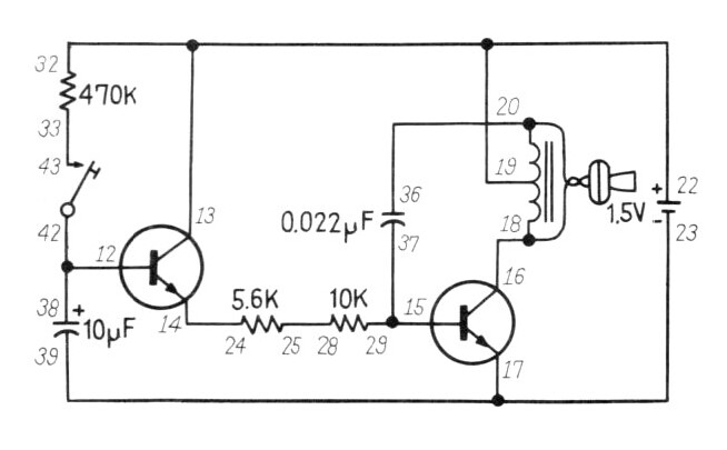
To allow the tone to change when the key is pressed and released, as described in the manual, I have placed the 470K resistor in parallel with the 10uF capacitor. This allows the capacitor to discharge when the key is released and slowly turns off the transistor. Without a suitable path through which to discharge, the capacitor is able to maintain the required charge to keep the first transistor in the active region.
I have replaced the 470K resistor, that we have now repurposed, with the 100K resistor. This shortens the charge time of the 10uF capacitor. This substitution, and the expected effect, is listed as a suggested extension in the 60-in-1 project manual linked above.
You can try the simulation yourself here: https://www.falstad.com/circuit/circuitjs.html
The simulation stores only the last 10 seconds of audio (on a rolling basis) and no audio is played during the simulation run. To play the simulated output you must press the "Play Audio" button.
Note that the circuit starts in the "off" state until the 10uF capacitor is charged via the key switch (and 100K resistor). Once released, the simulated circuit falls into a state of self-oscillation indefinitely. With my physical 30 in One kit, releasing the key allows the capacitor to fully discharge and the tone to cease. If desired, correct switch-off characteristics can be replicated in the simulated circuit by adding the 680 ohm resistor (also available in the project lab kit) between the base of the transistor and the positive terminal of the 10uF capacitor.
Scans
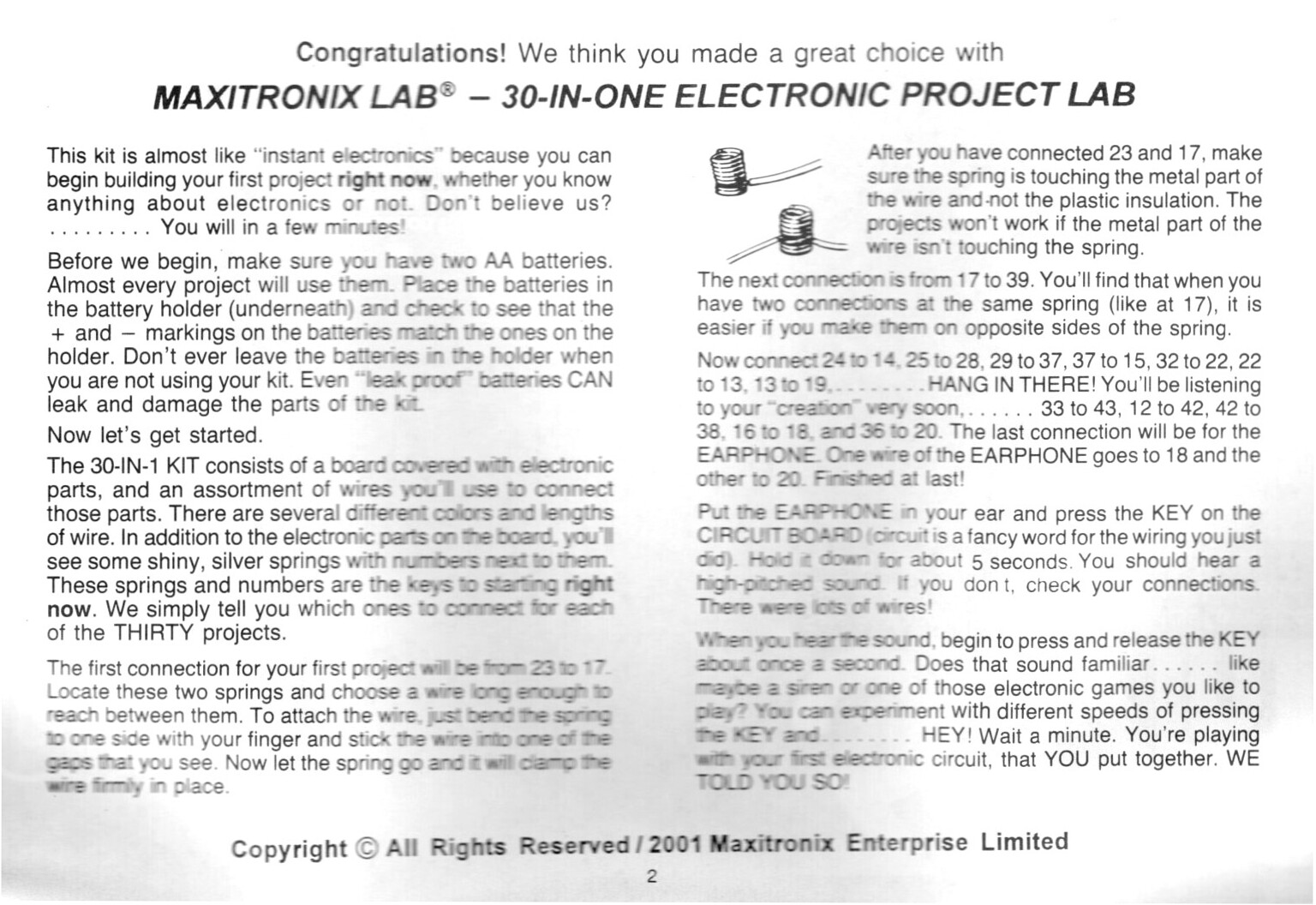
- Maxitronix-30in1-01-instructions.jpg
- Maxitronix-30in1-01-schematic.jpg
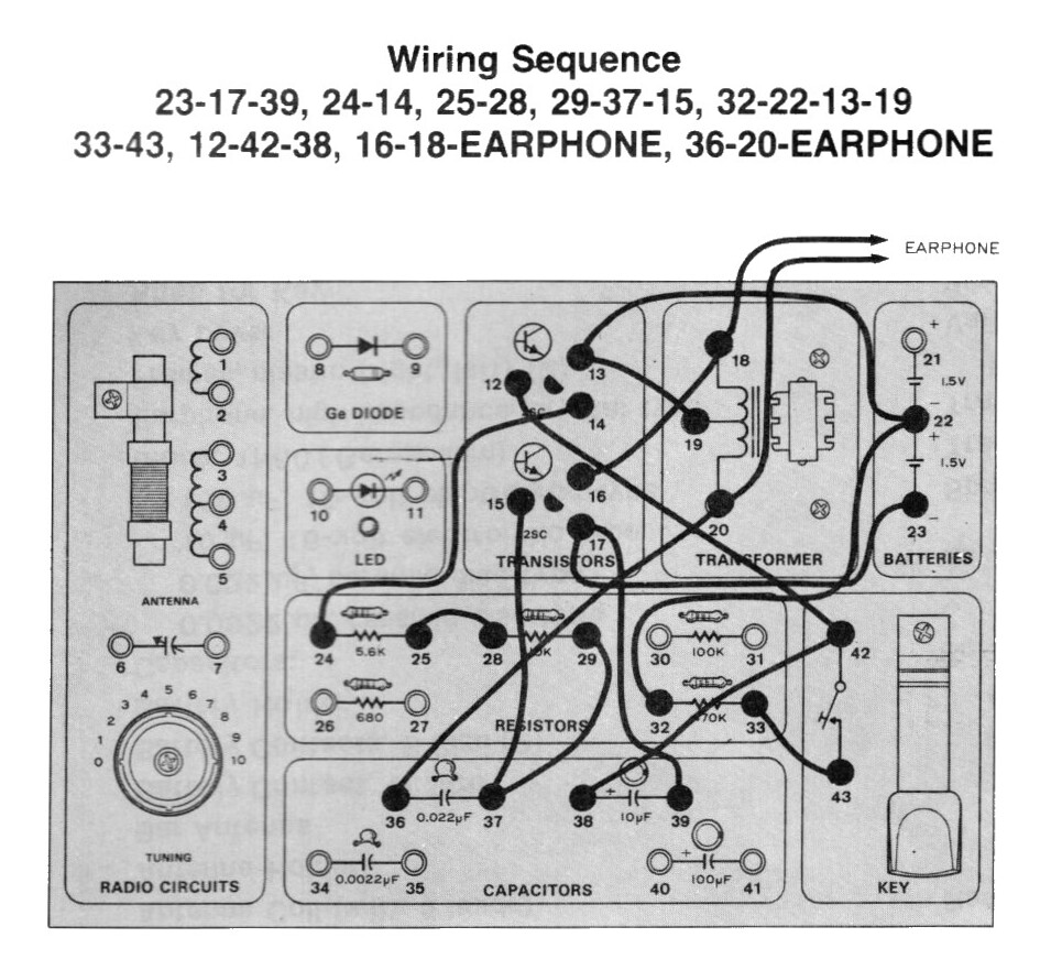
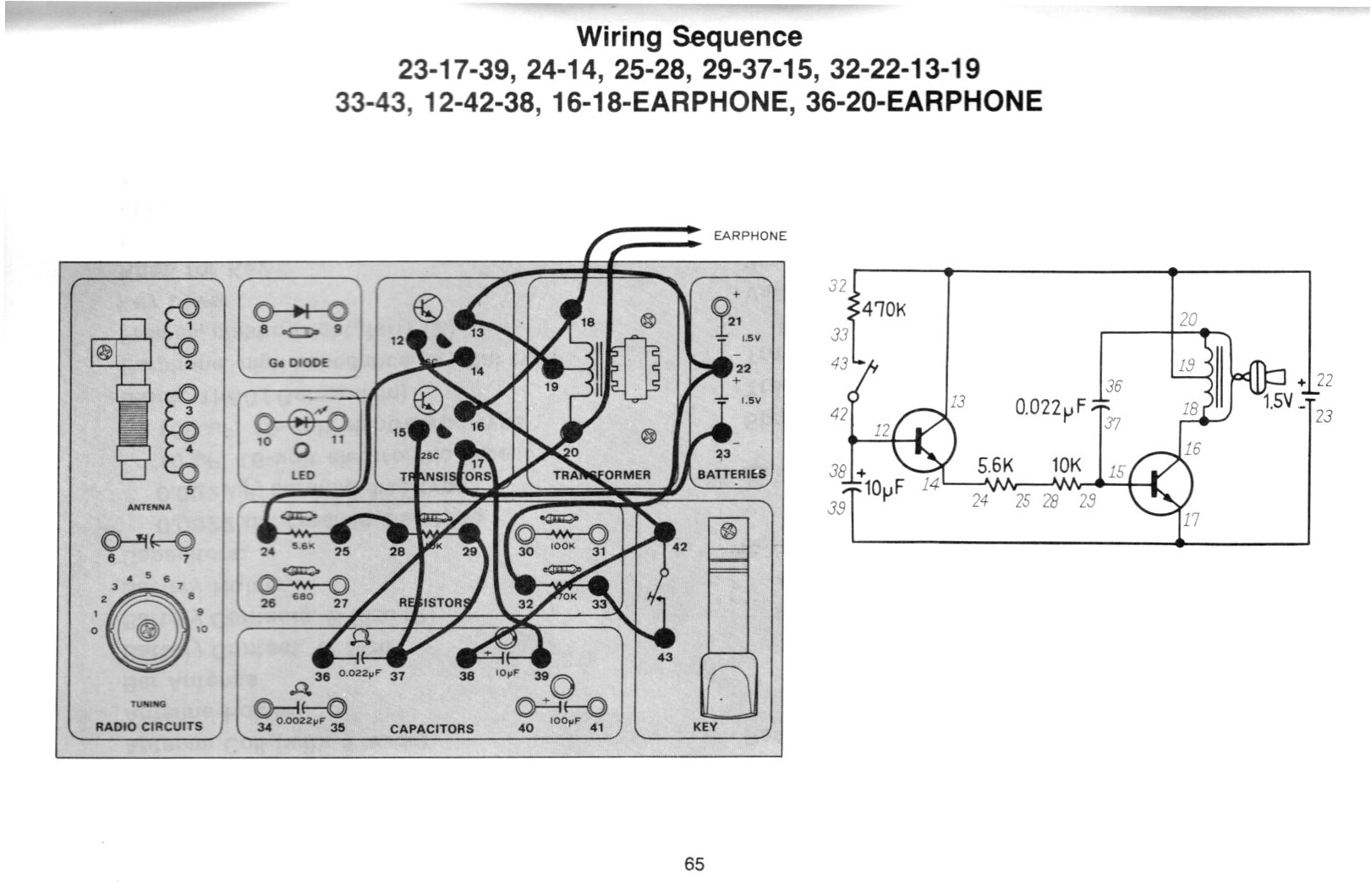
- Maxitronix-30in1-01-wiring.jpg
- Maxitronix-30in1-01.jpg
Maxitronix-30in1-01-instructions.jpg
Maxitronix-30in1-01-schematic.jpg
Maxitronix-30in1-01-wiring.jpg
Maxitronix-30in1-01.jpg
KiCad
To create the KiCad file, start a new project and edit the schematic, then:
- V1 is Simulation_SPICE:VDC; 1.5V DC
- V2 is Simulation_SPICE:VDC; Device type: Pulse: y1=-5 y2=5 td=1u tr=1u tf=1u tw=0.5 per=1
- 0 is Simulation_SPICE:0 (connect to V1 and V2, this is GND)
- R1 is Device:R, 470k
- R2 is Device:R, 5.6k
- R3 is Device:R, 10k
- Q1 Simulation_SPICE:NPN
- Q2 Simulation_SPICE:NPN
- C1 is Device:C_Polarized; 10uF
- C2 is Device:C; 0.022uF
- autotransformer is modeled as:
- L1 Device:L; 960mH
- L2 Device:L; 960mH
- .K1 L1 L2 0.98 (Draw Text)
- piezo earphone is modeled as:
- C3 is Device:C; 8nF
- R4 is Device:R, 100
- S1 is Simulation_SPICE:SWITCH; thr=0 ron=1 roff=10M
- connect V2 to S1
- connect S1 between C1 and R1
- netlist "SIG" connected to S1 upper
- netlist "OUT" connected to R4 lower
In SPICE Simulator add TRAN Transient Analysis as:
.tran 100u 20
